Digital Flow Meters 9000MP
 Eldridge Products, Inc. Series 9000MP Multipoint Systems are designed to measure air and other gas flows where two or more sensing points are required due to large cross-sectional areas. The Series 9000MP System now incorporates an internal Modbus network that provides the user with unrivaled control, power, and flexibility for measuring flows in large ducts, stacks, and flow conduits. The system has a sensor accuracy of ± (1% of reading + .5% of full scale) over a calibration turndown ratio of 100:1 based on full scale velocities as low as 1500 SFPM (7.6 NMPS).
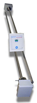
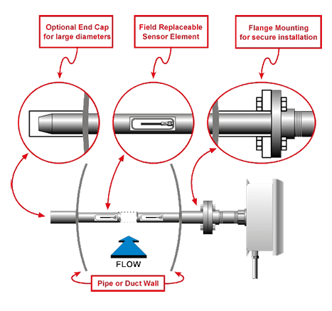
Each Series 9000MP Multipoint System includes at least one flow transmitter probe assembly and a Series 9600MP System Control Panel (SCP). The probe assembly is the heart of the multipoint system. The probe assembly consists of two or more flow sensors (maximum of 5 sensors per probe) mounted in a 1½" OD probe shaft. Each sensor is matched to its own microprocessor and is individually calibrated and linearized. The microprocessor for each sensor is mounted outside of the flow duct in an enclosure at the end of the probe shaft.
The linearized flow signal from each sensor is sent via Modbus communications to the SCP. The linearized intput signals from the multiple sensors in the probe(s) are then averaged by the SCP microprocessor. Typically, the system's averaged output signal is transmitted to a control room or data acquisition system. However, the Modbus commincations also allow the interrogation of each sensor, if necessary.
The chart below is a sample guideline to the number of traverse points suggested for a circular duct. Large diameter stacks may require more probes, and EPI™ has successfully developed strategies for accurate flow measurement in stacks where fully traversing the large diameter is impractical. Once the average flow rate is determined, the factory can specify the minimum number of sensors in a Series 9000MP System. The greater the number of points measured, the greater the accuracy of the final average flow rate. Also note that the accuracy of any one point becomes of less importance to the final accuracy of the total flow rate as the number of points is increased because of the averaging method utilized. If the point of average flow cannot be determined, then a simple rule is to specify the number of points based on the chart below.
| Duct Diameter | Suggested Number of Probes | Suggested Sensors per Probe | Total Number of Sensors |
| 8" - 18" | 1 | 2 | 2 |
| 18" - 24" | 1 | 4 | 4 |
| 24" - 36" | 2 | 2 | 4 |
| 36" - 60" | 2 | 4 | 8 |
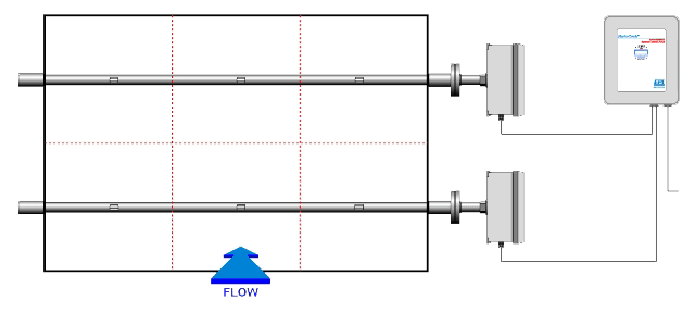
In square or rectangular ducts, the sensors are typically positioned in equal areas:
The Eldridge Air Purge System (APS) provides a means of cleaning the sensors in applications where particulates cause problems. A stainless steel tube is mounted on the downstream side of the probe support with a pair of outlet holes positioned at each sensor. The tube is connected to a tap located on the mounting flange. After basic installation of the multipoint system is complete, a pressurized gas line (typically compressed air) is connected to the tap. The gas is released at set intervals to clean the sensor surface of any accumulated particulates. The frequency and duration of the purging gas stream can be controlled by the multipoint system’s relays based on elapsed flow or by an external timing device supplied by the customer.
Specifications
| Linear signal output | 0–5 VDC & 4–20 mA |
| Relay Output | Two 1-amp @ 30 VDC, user-selectable alarm functions |
| Signal Interface | RS232 & RS485 Modbus RTU |
| Sensor accuracy including linearity (Ref.: 21°C): | ± (1% of Reading + (0.5% + .02%/°C of Full Scale)) |
| Sensor repeatability | ± 0.2% of Full Scale |
| Sensor response time | 1 second (time constant per step change) |
| Turn down ratio | 100:1 (15 SCFM/FT2 minimum Reading) |
| Electronics temperature range | -40°–85°C (-40°–185°F) |
| Gas temperature range | -40°–200°C (-40°–392°F) |
| Gas temperature effect | 0.02% /°C |
| Gas pressure effect | Negligible over ±20% of absolute calibration pressure |
| Pressure rating maximum | 500 PSI Std., >500 special |
| 9600MP Control Panel input power | 24VDC @ 250mA optional 115VAC 50/60 Hz optional 230VAC 50/60 Hz |
| 9600MP Control Panel power requirements | 5 Watts or less |
| 9600MP Control Panel enclosure | NEMA 4X fiberglass 10" x 12" x 6" consult factory for optional aluminum |
| 9000MP Probe Assembly enclosure | NEMA 4X fiberglass 8" x 10" x 4" consult factory for optional aluminum |
| RAM Back-up | Lithium Battery, 2.5–3.5v, >10 years |
| Wetted materials: | 316SS, including sensor |
| Standard temperature & pressure (STP) | 70° F & 29.92" Hg |
| (Air .075 lb/cubic foot) | |
| NIST traceable calibration | Standard |
If you require further information on this product or would like a quotation, please contact dp-flow on:
email: sales@dp-flow.co.uk
sales +44(0)1608 544222
Supplied by DP-Flow